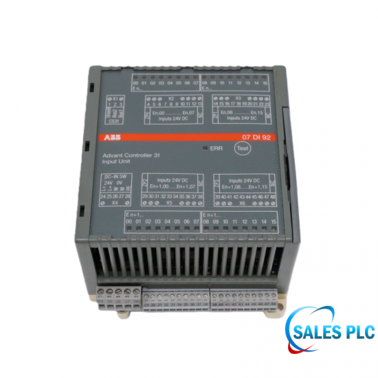
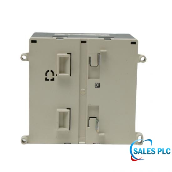
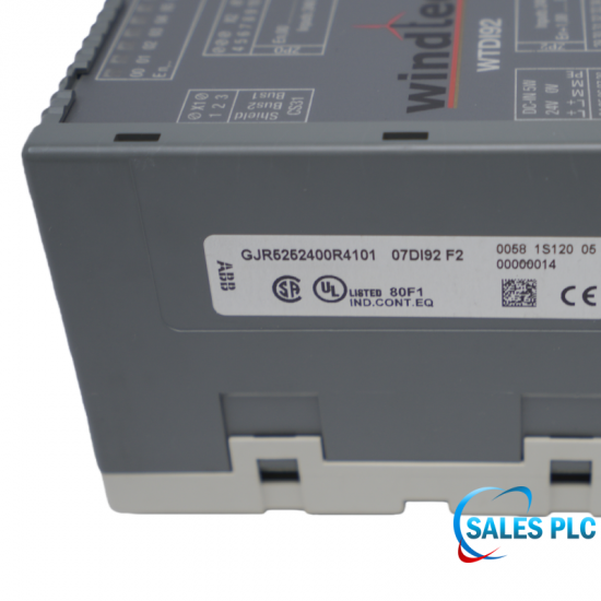
07DI92
Digital Input Module · GJR5252400R0101
Lifecycle note: Preserve the CS31 address allocation, input-reference wiring and grounding plan before replacing the module.
Product Condition
Original New with One Year WarrantyParts Available
In Stock and Same Day ShippingDelivery Mode
Shipping via DHL Fedex or UPS etcEmail:
sales17@amikon.cnWhatsapp/Mob:
+86 153 5940 8275Digital Input Module · Advant Controller 31
ABB 07DI92, order number GJR5252400R0101, is a CS31 remote digital-input module with 32 inputs for 24 V DC signals. The inputs are arranged as four groups of eight, with group-to-group isolation and isolation from the remainder of the unit. The module itself uses a 24 V DC supply and occupies two digital input addresses on the CS31 system bus.
The documented logic-zero interval is −30 to +5 V and the logic-one interval is +13 to +30 V. Typical input delay is 7 ms and typical input current is 7 mA at 24 V. These figures define the sensor-interface review: the input voltage, available sensor drive and off-state leakage must be checked together, particularly for electronic proximity sensors and long field wiring.
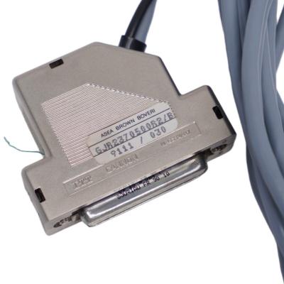
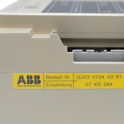
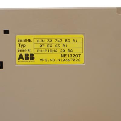
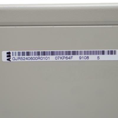
For a maintenance replacement, retain the installed addressing and terminal allocation, verify the four input-reference connections and preserve the control-system grounding arrangement. The module needs no stored I/O configuration data, but the controller project and hardware address must still agree. Supplier acceptance should identify the complete GJR order number, count the removable terminal blocks and test the required input points against the original wiring schedule.
| Manufacturer / model | ABB / 07DI92 |
|---|---|
| Order number | GJR5252400R0101 |
| Input count / grouping | 32 inputs / 4 groups of 8 |
| Supply / signal nominal voltage | 24 V DC / 24 V DC |
| Logic-zero voltage | −30 to +5 V |
| Logic-one voltage | +13 to +30 V |
| Typical input delay | 7 ms |
| Input current at 24 V | Typically 7 mA per channel |
| Maximum module supply current | 0.15 A |
| Supply terminal load rating | Maximum 4.0 A |
| CS31 interface / addressing | 1 isolated EIA RS485 interface / 2 digital input addresses |
| Operating temperature | 0 to +55 °C |
| Dimensions / mass | W 120 × H 140 × D 85 mm / 450 g |
| Signal / supply conductor size | Signal max. 1.5 mm²; supply and bus max. 2.5 mm² |
Preserve the CS31 address allocation, input-reference wiring and grounding plan before replacing the module.
It lies between the documented logic-zero and logic-one bands. Do not use it as a guaranteed state in an acceptance test. Investigate sensor drive, voltage drop and leakage, then restore a signal level within the specified band.
Measure the actual input voltage relative to its group reference with the sensor off, and compare the sensor’s leakage specification with the module input characteristics. The off state must remain within the documented zero band; an unloaded sensor voltage alone does not prove compatibility.
No. The manual separates a maximum module current consumption of 0.15 A from a maximum 4.0 A load rating for the supply terminals. Use the former for module demand and the latter as a terminal-loading limit; neither is a digital-output rating.
No. The −30 V lower limit describes the signal-input zero range, not a permissible reversed operating supply. Wire the nominal 24 V DC module supply to its designated polarity and follow the grounding drawing.
The manual describes all LEDs being on during automatic initialization. A brief startup illumination is therefore different from 32 confirmed active process inputs. Evaluate field states after initialization and verify them in the controller.
The manual states that the error LED flashes when the CS31 system bus is not running. Check the bus master, bus wiring and communication state rather than assuming the indication identifies a faulty individual input sensor.
The stated delivery scope includes one 5-pole block and one 3-pole block at 5.08 mm pitch, plus four 10-pole blocks at 3.81 mm pitch. Check that the offered spare includes the agreed pieces and that their pitch and terminal condition match.
No. 07DI92 is a digital-input module and requires no I/O configuration data internally. It is not the configurable 07DC92 I/O module. Confirm the installed hardware identity when a spare request describes bidirectional channels.
Send the model, complete part number, quantity, destination and nameplate photo. We will verify identification details before confirming availability and lead time.
Official PDF: ABB 07DI92 Official Manual Extract. File size is below 1 MB; verify the exact installed hardware and configuration before use.


Visit us
32D Guomao Building, No.388, Hubin South Road, Siming District
Please read on, stay posted, subscribe, and we welcome you to tell us what you think.
Disclaimer : Salesplcauto sells new and surplus products and develops channels for purchasing such products. This website has not been approved or recognized by any of the listed manufacturers or trademarks. Salesplcauto is not an authorized distributor, dealer, or representative of the products displayed on this website. All product names, trademarks, brands, and logos used on this website are the property of their respective owners. The description, explanation, or sale of products with these names, trademarks, brands, and logos is for identification purposes only and is not intended to indicate any association with or authorization from any rights holder.
Copyright @2026 SalesPlc Limited. Sitemap
/ Blog
/ XML
/ Terms And Conditions
/ Privacy Policy
 Network Supported



About Us
Reliable Industrial Automation Parts, Global Supply Support SALES PLC works with a broad network of qualified suppliers to provide industrial automation components that meet our customers’ requirements for quality, availability, price, and delivery time. Our product portfolio covers PLC, DCS, HMI, control systems, safety systems, drives, communication modules, and other critical spare parts from leading brands, including Siemens, Emerson, Invensys Triconex, HIMA, GE, ABB, Honeywell, and Bently Nevada. More Than Products — Complete Supply Solutions Our strength goes beyond product sourcing. We work closely with end users, system integrators, maintenance teams, and industrial partners to identify suitable replacement parts and practical procurement solutions. Through integrated purchasing and online support, customers can send inquiries and place orders throughout the year. Our experienced team responds quickly and helps reduce downtime caused by unavailable or obsolete equipment. Our Team Our experienced team brings together product specialists, sourcing professionals, sales consultants, and customer service staff. We work together to provide clear communication and dependable support at every stage of the order. Growing Together for More Than 20 Years For more than 20 years, SALES PLC has continued to grow with the support and trust of customers, suppliers, and business partners around the world. Every project, inquiry, and partnership has helped us improve our service. Looking ahead, we remain committed to providing dependable products, responsive communication, and professional industrial automation solutions. Thank you to every customer and partner who has supported our journey. We look forward to building a stronger and more successful future together. Sustainable Partnerships SALES PLC believes in building long-term, mutually beneficial relationships with customers and suppliers. We focus on honest communication, responsible sourcing, continuous improvement, and reliable service. As industrial technology continues to evolve, we keep expanding our product knowledge and supplier network to support new systems, legacy equipment, and replacement-part requirements. Contact SALES PLC Our team is available during working hours to answer your questions, check product availability, and prepare a quotation.
Where to Find Us
 32D Guomao Building, No.388, Hubin South Road, Siming District
 +86 18150117685
 sales1@amikon.cn
Follow Us