DATX131
Rotor-Feedback Circuit Board · Requested order 3ASC25H215
Lifecycle note: Match the installed drawing and board label. Requested order and electrical ratings require confirmation before replacement.
ItemNO:
3ASC25H215Product Condition
Original New with One Year WarrantyParts Available
In Stock and Same Day ShippingDelivery Mode
Shipping via DHL Fedex or UPS etcEmail:
info@amikon.cnWhatsapp/Mob:
+86-18020776786Rotor-Feedback Circuit Board · ASTAT
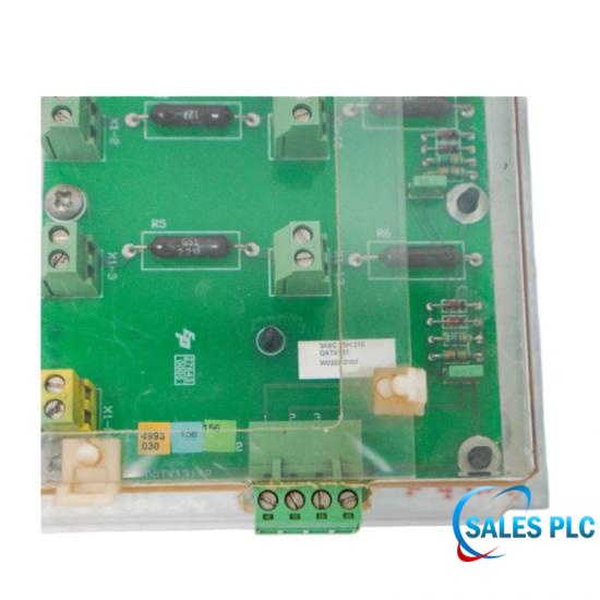
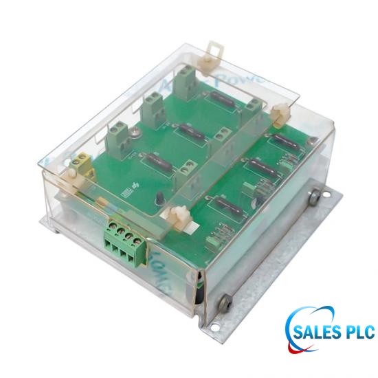
ABB DATX131 is identified in the feedback-module drawing within the ABB ASTAT manual. The manual assigns this rotor-measurement drawing to DARA 1001 / 1010 assemblies. The requested purchasing reference is 3ASC25H215; the selected original pages identify DATX131 but do not independently verify that order number.
Drawing 3ASC25H200, sheet 9, shows terminal groups X1:1–3 and X1:11–13, connection X2 and PE, and assemblies A4.1–A4.4 associated with feedback references RM1–RM4. These are circuit identifiers, not numerical performance ratings. Four assemblies in a drawing must not be described as four analog channels on a single board.
For system integration and MRO sourcing, compare the installed board label, assembly reference and wiring revision with the original drawing. Voltage limits, current limits, division ratio, accuracy and environmental ratings remain to be confirmed before selecting or testing a replacement. Qualified personnel should use the approved site procedure and obtain the missing manufacturer data rather than apply generic I/O specifications.
| Manufacturer | ABB |
|---|---|
| Model | DATX131 |
| Requested order number | 3ASC25H215 — nameplate / manufacturer confirmation required |
| Documented application | ASTAT rotor-measurement feedback circuit |
| Drawing context | DARA 1001 / 1010 assemblies |
| Drawing reference | 3ASC25H200, sheet 9; not an order number |
| Terminal labels, first group | X1:1, X1:2, X1:3 |
| Terminal labels, second group | X1:11, X1:12, X1:13 |
| Other connection labels | X2 and PE |
| Assembly references | A4.1–A4.4: four drawn assemblies, not four channels per board |
| Feedback circuit references | RM1–RM4 |
| Voltage and current ratings | To be confirmed; not specified by the selected drawing |
| Division ratio and accuracy | To be confirmed; resistor values are not established here |
| Environmental / isolation ratings | To be confirmed; do not infer from other ASTAT modules |
Preserve the ASTAT drawing revision and terminal identification. Confirm the board nameplate and missing electrical ratings before replacement or testing.
No. A4.1–A4.4 identify four separate assemblies shown on the system drawing. This does not establish a per-board channel count, sampling specification or analog input range. Keep assembly quantities separate from module performance in the bill of materials.
They are terminal identifiers. The numbers do not mean 11 V, 12 V or 13 V. Preserve the full connector-and-terminal notation and match it to the installed drawing revision rather than shortening it to a bare number.
Not by themselves. The selected drawing does not establish the resistor values and tolerances needed to calculate a verified ratio. Obtain the correct component data and approved test limits before specifying an acceptance measurement.
No. Neither range is established for DATX131 by these selected manufacturer pages. A generic industrial-control-board description is not evidence of an analog I/O range; leave those values unconfirmed until model-specific documentation is available.
No. A shared drawing label does not establish that stocked variants or revisions are interchangeable. The integrator must reconcile the installed assembly, board label and approved spare-part mapping before accepting a substitution.
Do not assume that equivalence. Preserve the PE designation and obtain the applicable installation and grounding instructions. This circuit-reference extract is not sufficient authority to alter bonding or signal-reference connections.
It is the drawing reference on sheet 9, not proof of the board order number. The requested purchasing reference 3ASC25H215 must be checked against the physical nameplate or a manufacturer spare-parts record before order release.
Record the visible DATX131 marking and revision, retain photographs, and place electrical acceptance on hold until the applicable ratings and test method are confirmed. Do not energize the spare using ratings borrowed from adjacent ASTAT power-supply modules.
Send the model, complete part number, quantity, destination and nameplate photo. We will verify identification details before confirming availability and lead time.
Manufacturer reference: ABB ASTAT manual, original PDF pages 225 and 242. Three-page Sales PLC reference PDF, approximately 106 KB. The drawing verifies DATX131 identification, not the requested order or complete electrical ratings.


Visit us
32D Guomao Building, No.388, Hubin South Road, Siming District
Please read on, stay posted, subscribe, and we welcome you to tell us what you think.
Disclaimer : Salesplcauto sells new and surplus products and develops channels for purchasing such products. This website has not been approved or recognized by any of the listed manufacturers or trademarks. Salesplcauto is not an authorized distributor, dealer, or representative of the products displayed on this website. All product names, trademarks, brands, and logos used on this website are the property of their respective owners. The description, explanation, or sale of products with these names, trademarks, brands, and logos is for identification purposes only and is not intended to indicate any association with or authorization from any rights holder.
Copyright @2026 SalesPlc Limited. Sitemap
/ Blog
/ XML
/ Terms And Conditions
/ Privacy Policy
 Network Supported



About Us
Reliable Industrial Automation Parts, Global Supply Support SALES PLC works with a broad network of qualified suppliers to provide industrial automation components that meet our customers’ requirements for quality, availability, price, and delivery time. Our product portfolio covers PLC, DCS, HMI, control systems, safety systems, drives, communication modules, and other critical spare parts from leading brands, including Siemens, Emerson, Invensys Triconex, HIMA, GE, ABB, Honeywell, and Bently Nevada. More Than Products — Complete Supply Solutions Our strength goes beyond product sourcing. We work closely with end users, system integrators, maintenance teams, and industrial partners to identify suitable replacement parts and practical procurement solutions. Through integrated purchasing and online support, customers can send inquiries and place orders throughout the year. Our experienced team responds quickly and helps reduce downtime caused by unavailable or obsolete equipment. Our Team Our experienced team brings together product specialists, sourcing professionals, sales consultants, and customer service staff. We work together to provide clear communication and dependable support at every stage of the order. Growing Together for More Than 20 Years For more than 20 years, SALES PLC has continued to grow with the support and trust of customers, suppliers, and business partners around the world. Every project, inquiry, and partnership has helped us improve our service. Looking ahead, we remain committed to providing dependable products, responsive communication, and professional industrial automation solutions. Thank you to every customer and partner who has supported our journey. We look forward to building a stronger and more successful future together. Sustainable Partnerships SALES PLC believes in building long-term, mutually beneficial relationships with customers and suppliers. We focus on honest communication, responsible sourcing, continuous improvement, and reliable service. As industrial technology continues to evolve, we keep expanding our product knowledge and supplier network to support new systems, legacy equipment, and replacement-part requirements. Contact SALES PLC Our team is available during working hours to answer your questions, check product availability, and prepare a quotation.
Where to Find Us
 32D Guomao Building, No.388, Hubin South Road, Siming District
 +86 18150117685
 sales1@amikon.cn
Follow Us