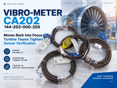
VIBRO-METER CA202 144-202-000-205 is returning to procurement discussions as turbine, compressor and power-generation teams reassess legacy vibration-monitoring chains. This engineering news briefing explains the sensor's charge-output architecture, signal-conditioning requirements, installation risks and the exact part-number checks maintenance and MRO buyers should complete before ordering a replacement. Rotating Equipment Reliability News VIBRO-METER CA202 144-202-000-205 Moves Back into Focus as Turbine Teams Tighten Sensor Verification A practical engineering and procurement briefing for legacy vibration measurement chains in power, petrochemical, LNG and rotating-equipment plants. ReviewedSeptember 9, 2026 AuthorFrida Introduction A Small Device with a Large Maintenance Consequence September 2026 — Shutdown planners are revisiting the VIBRO-METER CA202 144-202-000-205 as ageing turbine and compressor fleets make exact sensor identification more important. A vibration channel may include the charge-output accelerometer, integral cable, charge converter, monitor input and alarm logic. Replacing one element without checking the chain can create a believable but incorrect signal. What the CA202 Actually Is The CA202 is a piezoelectric accelerometer, not a complete monitoring module. Its symmetrical shear-mode element produces charge proportional to acceleration. The insulated two-pin system provides differential charge output and requires a compatible charge converter before the measurement reaches a monitoring system. Nominal sensitivity100 pC/g ±5% Frequency response0.5–6000 Hz, ±5% Dynamic range0.01–400 g peak Signal2-pin differential charge output CA202 technical signal chain and the key specifications engineers should verify against the installed configuration. Why CA202 Remains Important in Critical Rotating Equipment Bearing-Housing Vibration Where Heat and Contamination Matter On turbines, generators, compressors and pumps, casing acceleration can reveal imbalance, looseness, misalignment, bearing degradation and rubs. The CA202 sensor is specified for continuous operation from −55 to +260°C; the integral cable has a separate −55 to +200°C limit. Its welded stainless-steel housing and protection hose resist humidity, water, steam, oil and industrial contaminants. Why the Brand Architecture Matters VIBRO-METER’s advantage is measurement-chain continuity. The accelerometer, low-noise cable, conditioner and protection input operate as one signal path. In power, refinery and LNG assets, that continuity helps preserve alarm interpretation and historical trends without introducing an unverified sensor-to-monitor combination. One Model Can Carry Many Different Order Numbers VIBRO-METER Type/Model and Part Number are not interchangeable identifiers. A family name such as CA202, IPC704 or MPC4 describes the product platform; the complete order number identifies the configuration that procurement and engineering must match. 01Model identifies the...
View More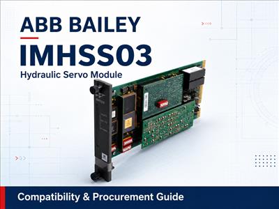
Avoid Costly Downtime: ABB Bailey IMHSS03 Technical, Compatibility & Procurement Guide Turbine valve control is not an area where maintenance teams can afford an uncertain spare. In ABB Bailey INFI 90 and Harmony rack turbine-control installations, the IMHSS03 Hydraulic Servo Module provides the interface between the controller and the hydraulic actuator that positions critical valves. A module fault, an incorrect replacement, or an incomplete commissioning check can therefore affect turbine availability and extend a planned or unplanned outage. This guide explains what the IMHSS03 does, which technical details matter during replacement, how the newer ABB SPHSS13 fits into the lifecycle strategy, and what procurement teams should verify before issuing a purchase order. Quick answer An IMHSS03 should never be selected by model name alone. Confirm the controller configuration, Function Code 55 or 150, termination hardware, jumper and dip-switch settings, LVDT arrangement, servo or I/H output requirements, redundancy design, and commissioning procedure. ABB has identified the SPHSS13 as a direct replacement path for earlier HSS modules, including the IMHSS03, but “direct replacement” does not remove the need for an application-level compatibility review. .imhss-widget { --imhss-navy: #102d4f; --imhss-blue: #2f6df6; --imhss-blue-dark: #245d85; --imhss-red: #d71920; --imhss-green: #2eae61; --imhss-orange: #f59e0b; --imhss-text: #243447; --imhss-muted: #667587; --imhss-line: #dce4eb; --imhss-panel: #f5f7fa; --imhss-white: #ffffff; } .imhss-widget, .imhss-widget * { box-sizing: border-box; } .imhss-demo-shell { width: min(100%, 980px); margin: 0 auto; } .imhss-demo-intro { margin: 0 0 14px; color: var(--imhss-muted); font-size: 14px; line-height: 1.6; } .imhss-widget { --stroke: 50%; overflow: hidden; border: 1px solid #e2e8ef; border-radius: 28px; background: var(--imhss-panel); box-shadow: 0 18px 48px rgba(16, 45, 79, 0.10); } .imhss-widget__topbar { display: grid; grid-template-columns: minmax(210px, 1fr) auto auto; align-items: center; gap: 14px; min-height: 66px; padding: 10px 18px; border-bottom: 1px solid var(--imhss-line); background: rgba(255, 255, 255, 0.72); } .imhss-widget__brand { display: flex; align-items: center; gap: 10px; min-width: 0; color: #0b1727; font-size: 14px; font-weight: 700; white-space: nowrap; } .imhss-widget__diamond { width: 11px; height: 11px; flex: 0 0 auto; border: 2px solid #ffffff; background: var(--imhss-blue); box-shadow: 0 0 0 1px var(--imhss-blue); transform: rotate(45deg); } .imhss-tabs { display: inline-flex; gap: 4px; padding: 4px; border-radius: 999px; background: #e9edf2; } .imhss-tab { min-width: 128px; border: 0; border-radius: 999px; padding: 9px 18px; background: transparent; color: #111827; cursor: pointer; font: 700 13px/1 Arial, Helvetica, sans-serif; transition: background 180ms ease, color 180ms ease, box-shadow 180ms ease; } .imhss-tab[aria-selected="true"] { background: var(--imhss-blue); col...
View More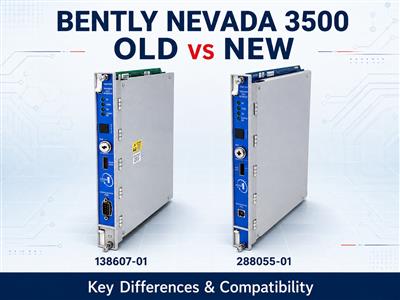
BENTLY NEVADA 3500 GUIDE Bently Nevada 3500 Old vs. New Versions What changed, which components must be checked, and when a newer module can directly replace an older one. Quick answer: A newer 3500 module may provide form, fit and functional compatibility, but there is no universal “perfect replacement.” The complete part number, rear I/O module, rack interface, firmware, configuration, connected sensor and required approvals must all be verified. The Bently Nevada 3500 Machinery Protection System has been used for decades to monitor turbines, compressors, pumps, generators and other critical rotating equipment. Because many installed racks remain in service for years, maintenance teams often encounter different hardware revisions within the same 3500 family. Some modules have green circuit boards, while newer units use blue boards. Some racks still use the 3500/20 Rack Interface Module, while newer configurations use the 3500/22M Transient Data Interface. There are also standard and “M” versions of several monitoring and relay modules. These differences make replacement checks more important than simply matching the family name printed on the front panel. 1. What Does “Old” and “New” Mean in the 3500 System? The terms “old version” and “new version” can refer to several different types of change. They should not be treated as one single upgrade path. Version Description What It Usually Refers To Replacement Impact Green vs. blue PCB A manufacturing and electronics revision, including the transition to RoHS-compliant lead-free boards. Board color alone does not confirm compatibility. 3500/20 vs. 3500/22M A change from the Rack Interface Module to the Transient Data Interface architecture. Requires a rack-level compatibility review and the correct rear I/O. Non-M vs. M-series A module-generation or functionality change within selected 3500 monitor families. Not automatically a one-for-one replacement. 3500 vs. Orbit 60 A migration from the 3500 platform to a different monitoring platform. A system retrofit, not a plug-in card replacement. Manufacturing Revision: Green and Blue Circuit Boards Earlier 3500 modules commonly used green printed circuit boards. Bently Nevada later refreshed the electronics and board layouts to meet RoHS requirements, replacing green boards with blue lead-free boards. The update also supported component-lifecycle management and modern manufacturing processes. This was not a change to the basic purpose of the 3500 system. However, PCB color should never be used as the only replacement criterion. The module part number, hardware revision, I/O type and firmware still need to be checked. Interface Architecture: RIM and TDI Older racks may use a 3500/20 Rack Interface Module, or RIM. Current configurations normally use the 3500/22M Transient Data Interface, or TDI. The TDI provides the main connection between the rack and 3500 Configuration Software, display systems and System 1 condition-monitoring software. It also provide...
View More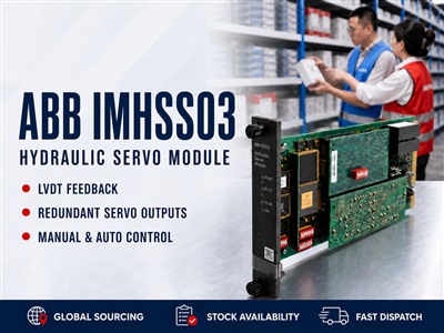
ABB Harmony Turbine Control · Technical Guide ABB IMHSS03 Hydraulic Servo Module Functions, applications, technical specifications and a practical selection checklist for turbine-control systems. Module Type Hydraulic Servo System Family INFI 90 / Harmony Function Codes 55 or 150 The ABB IMHSS03 is an intelligent hydraulic servo module used for precision valve-position control in Bailey INFI 90 and ABB Symphony Harmony rack systems. It links the controller's position demand with a hydraulic actuator, drives a servo valve or I/H converter, and monitors actual movement through LVDT feedback. Important: The IMHSS03 is not a general-purpose analog output card. Correct selection depends on the controller function code, termination hardware, LVDT arrangement, output mode and approved field configuration. What Does the IMHSS03 Do? The module compares the requested actuator position with the actual position returned by an LVDT. It then regulates current to a servo valve or I/H converter until the hydraulic actuator reaches the required position. Controller Demand → IMHSS03 → Servo Valve / I-H Converter → Hydraulic Actuator → LVDT Feedback Processes hydraulic-actuator position demand Drives a direct servo valve or I/H converter Receives dual-secondary LVDT feedback Supports manual and automatic actuator control Provides raise, lower and trip-bias contact inputs Communicates with the controller through the I/O expander bus Where Is It Used? The IMHSS03 is primarily found in power-generation and industrial turbine packages that use hydraulic actuators for critical valve positioning. Application Area Typical Controlled Equipment Steam Turbines Throttle, governor, admission and steam-control valves Gas Turbines Fuel valves, inlet guide vanes and nozzle-angle mechanisms Power Generation Thermal, combined-cycle, cogeneration and captive power plants Process Industries Turbine-driven compressors and mechanical-drive packages Technical Specifications Manufacturer / Family ABB Bailey · INFI 90 / Symphony Harmony Model / Type IMHSS03 · Intelligent Hydraulic Servo Module Mounting One standard MMU slot Controller Access Hydraulic Servo Function Code 55 or 150 LVDT Inputs Two LVDT inputs, two secondaries each; four analog inputs total LVDT Excitation Two primary outputs · 400 Hz to 15 kHz Servo Outputs Four total; two selectable redundant protected analog outputs I/H Output 4–20 mA at 300 Ω max or 20–160 mA at 15 Ω max Contact Inputs Three isolated inputs: raise, lower and trip bias Operating Temperature 0°C to 70°C How to Select the Correct Module 1 Confirm the original nameplate Verify IMHSS03, hardware revision and all visible identification labels. → 2 Identify the host system Record the controller, MMU, I/O expander bus and installed system family. → 3 Check Function Code 55 or 150 Preserve the approved configuration, output range, gains, limits and calibration records. → 4 Verify termination hardware Confirm the termination unit, cable, jumpers, dipshunts, shiel...
View More
Technical Product Guide Triconex 3008 Main Processor: TMR Operation, Compatibility and Sourcing Guide A practical reference for engineers, system integrators, automation suppliers and MRO procurement teams evaluating a replacement Triconex 3008 module. At a glance: The Triconex 3008 is a main processor used in Tricon systems from version 9.6 onward. Correct replacement requires more than matching the front-panel model number: chassis, system version, firmware, project configuration and the condition of the existing system must also be reviewed. Technical Overview Model Triconex 3008 Module Type Main Processor Module Processor 32-bit Motorola MPC860 Clock Speed 50 MHz Memory 16 MB non-battery-backed DRAM System Application Tricon version 9.6 and later systems Architecture Triple Modular Redundancy (TMR) How the 3008 Fits into a TMR System A Tricon system uses three main processor channels. Each channel independently processes its portion of the application and exchanges information through the TriBus. This architecture allows the system to compare results and diagnose differences between channels. The processor module must therefore be treated as part of the complete configured system. A physically similar processor is not automatically a suitable replacement. Engineers should confirm the installed chassis, processor population, TriStation project, firmware and site replacement procedure before installation. Compatibility Checks Before Replacement Confirm the complete model: verify that the requirement is 3008 and not a different processor variant such as 3008N or 3009. Check the system release: confirm that the installed Tricon system and engineering documentation support the processor. Review firmware and revision: record available label, revision and firmware information before ordering. Verify the chassis: confirm the main chassis model and existing processor arrangement. Preserve the project: ensure the current TriStation project, configuration records and approved backups are available. Follow site procedures: replacement in a safety-related system must follow the plant's approved engineering, management-of-change and validation process. 3008 vs. 3008N Model suffixes should never be ignored. The 3008 and 3008N must not be treated as interchangeable solely because their base number is similar. Use the complete part number shown on the installed module, then confirm compatibility against the system documentation or with the responsible system integrator. Information to Include in an Enquiry A clear enquiry reduces identification errors and speeds up commercial confirmation. Please provide: Exact model number and clear label photographs Required quantity Current system version and chassis model Firmware or hardware revision requirements, if specified Required product condition Destination country and requested delivery date Related Triconex Products Browse the related Triconex processor, I/O and communication modules. Use the left and right con...
View More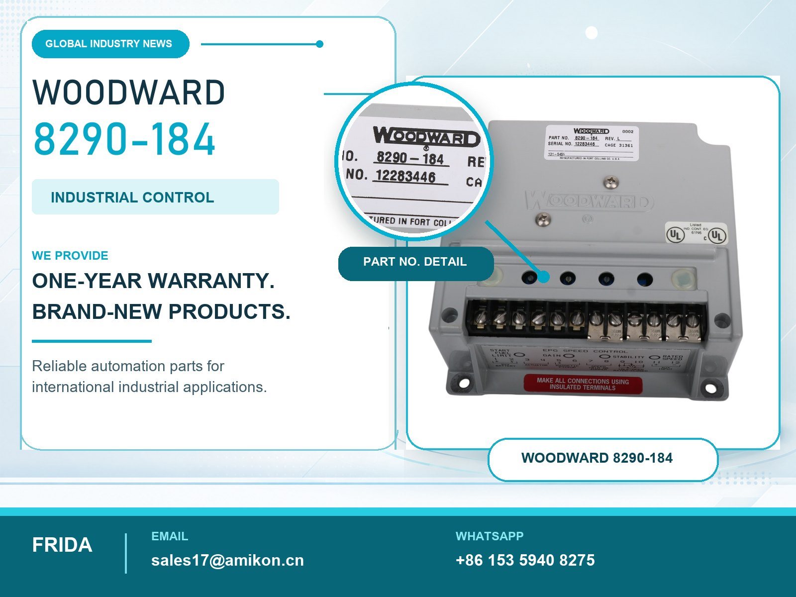
Woodward 8290-184 Brings Proven Speed Control Back into Focus for Critical Diesel and Turbine Assets Introduction Installed-Base Reliability Is Driving New Demand August 2026 — Industrial operators are reviewing the condition of aging governor systems as power reliability, emissions control and maintenance lead times become increasingly important. The Woodward 8290-184 has consequently returned to the attention of engineers responsible for diesel generator sets, turbine-driven equipment and packaged mechanical systems. This 24 VDC electronic speed control belongs to the Woodward EPG electrically powered governor family and is designed for isochronous operation with compatible 524 or 1724 actuators. Its continuing relevance reflects a practical reality: replacing a proven control component is often less disruptive than redesigning the complete prime-mover control architecture. A Small Controller with a Direct Production Impact A governor problem can prevent a standby generator from accepting load, destabilize a pump drive or extend the restart time of an essential utility package. For maintenance and procurement departments, the 8290-184 is therefore not simply another item among general automation spare parts. It is part of the closed-loop control path between the magnetic pickup, speed controller, actuator and fuel linkage. Correct identification matters because voltage, control mode, pickup-frequency range, actuator capacity, fuel type and starting strategy must agree with the installed equipment. 1. Woodward 8290-184 Combines Isochronous Control with Start-Fuel Limiting The Control Loop Is Built Around a Three-Component EPG System The Woodward EPG architecture combines an electronic speed control, a magnetic pickup and an electrically powered actuator. During operation, the magnetic pickup supplies a signal proportional to prime-mover speed. The controller compares that feedback with the selected speed reference and adjusts actuator position to correct the error. According to Woodward Product Specification 04106, part number 8290-184 is a 24 VDC isochronous controller for diesel or turbine applications using a 524 or 1724 speed-control actuator. The associated standard 24 VDC actuator references include 8256-021 for Model 524 and 8256-016 for Model 1724. Electrical Data Must Be Checked Before Replacement Approval The nominal 24 VDC input has a documented operating range of 20 to 32 VDC, with maximum power consumption specified at 95 W. Woodward calls for a battery charger capable of at least 5 A while the governor is energized and a 10 A slow-blow fuse or circuit breaker in the non-grounded battery lead. The magnetic pickup must provide at least 1.5 Vrms and typically 100 Hz during cranking. These details are important when investigating difficult starting, speed hunting or intermittent actuator response: replacing the controller will not correct an undersized power supply, poor grounding, weak pickup output or excessive cable voltage drop. Fr...
View More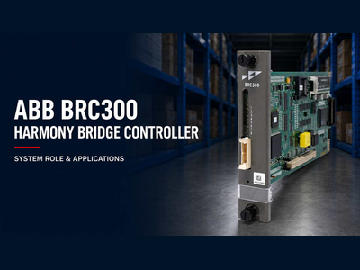
The ABB BRC300, identified by the full model number P-HC-BRC-30000000, is a Harmony Bridge Controller used within ABB process control architecture. Installed as a rack-mounted controller, it provides the processing and communication functions needed to connect control strategies with process I/O, other controllers, operator stations and higher-level system nodes. The supplied ABB Harmony documentation covers the BRC-100 and PBA-100 generation rather than the BRC300 specifically. It nevertheless provides a clear description of the role performed by a Harmony Bridge Controller and the surrounding modules that form the controller architecture. BRC300-specific processor, memory, power and firmware specifications should be checked against the correct BRC300 manual before engineering or replacement work. ROLEHarmony Bridge Controller MODELP-HC-BRC-30000000 I/O PATHSHnet + I/O Expander Bus AVAILABILITYRedundant architecture What Is the ABB BRC300? The BRC300 is identified on the supplied product as a Harmony Bridge Controller. In the Harmony architecture, the bridge controller works as the main processing unit between the process I/O layer and the rest of the control system. According to the Harmony Bridge Controller documentation, a BRC controller performs several central tasks: Collects process input data from connected I/O. Executes configured control algorithms. Sends control signals to process-level output devices. Exchanges process data with other controllers and system nodes. Accepts commands from operators and connected computers. Supports communication with both Harmony I/O blocks and Harmony rack I/O. Provides controller redundancy when installed with the required supporting hardware. In practical terms, the bridge controller converts field information into control actions. Measurements and status signals enter through the I/O system, the configured control strategy processes this data, and output instructions are returned to the relevant process devices. SYSTEM FLOW Where the controller sits PROCESS I/OHarmony blocks · Rack I/O → ABB BRC300Control execution · Data exchange → SYSTEM NODESControllers · Operators · Computers The BRC300 bridges field information and configured control actions across the Harmony architecture. How the Harmony Bridge Controller Fits into the System The Harmony architecture provides two main paths for connecting process I/O to a BRC controller. Harmony I/O Blocks Through Hnet Harmony I/O blocks communicate with the controller through Hnet. ABB defines Hnet as the communication path between a Harmony controller and Harmony I/O blocks. A Processor Bus Adapter is used to provide the physical connection between the BRC controller and the Hnet subsystem. The adapter also supports Hnet termination, isolation functions and the controller redundancy link. Examples of processor-based Harmony I/O blocks referenced in the manual include: AIN-120 AOT-150 CIO-100 DIO-400 Each I/O block consists of an I/O module and its associated...
View More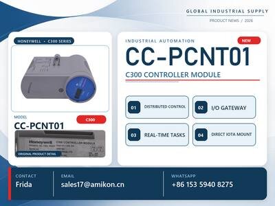
Installed-Base Demand Returns to the Foreground August 2026 — The Honeywell CC-PCNT01 51405046-175 C300 Controller is receiving fresh attention from engineers, maintenance managers, and buyers responsible for mature Experion PKS installations. This established controller executes regulatory, sequence, logic, and device-control strategies while linking field I/O, peer controllers, servers, and operator displays. A Replacement Decision with Production Consequences In a refinery, chemical complex, LNG terminal, power station, or pharmaceutical plant, a C300 failure can affect an entire unit. CC-PCNT01 sourcing must therefore address controller loading, firmware, Experion release, redundancy, I/O architecture, hardware revision, and migration strategy. A capable industrial automation parts supplier should provide identification evidence and compatibility support, not merely price and delivery. C300 Architecture Delivers Deterministic Process Control Two I/O Links and Fault-Tolerant Ethernet The CC-PCNT01 is the C300 control processor, with 51405046-175 used as the associated part number. Honeywell’s C300 capacity documentation identifies Fault Tolerant Ethernet as its control network and provides two I/O links. In the standard 50 ms Control Execution Environment, the controller can use a 375 Kbaud PM I/O link or a 750 Kbaud Series C I/O link. Device indexes are configurable from 1 through 510, while SNTP and PTPv2 provide synchronized time references for alarms, events, historian records, and sequence analysis. Control Resources Must Be Engineered, Not Estimated For the 50 ms configuration, Honeywell documents 5,500 Execution Units for user control, I/O, and communications, plus 14,852 Memory Units of CEE user memory. Module execution periods range from 50 ms to 60 seconds. Communication limits include 2,500 parameter-access responses per second, 4,000 subscribed parameters, and 3,000 reads or 1,500 writes per minute. These figures represent capacity ceilings rather than recommended continuous operating targets. Engineering teams must model CPU, memory, display, peer-to-peer, and I/O demand with adequate spare capacity. Redundancy Strengthens Process Availability Redundant control uses two IOTAs and an Ethernet STP redundancy cable. For a 50 ms CEE, Honeywell specifies a nominal 500 ms control-processing switchover interruption and up to 240 seconds for initial synchronization. Network or I/O-link conditions can extend the interruption, so redundancy should not be described as mathematically “zero downtime.” Honeywell’s brand advantage lies in coordination: CEE scheduling, FTE communications, peer data, I/O, diagnostics, and operator access work as integrated automation and control components within Experion PKS. Process Industries Continue to Depend on the CC-PCNT01 Refineries, LNG Plants, and Chemical Units Refinery duties include crude and vacuum distillation, hydrotreating, catalytic reforming, blending, tank transfer, flare monitoring, and utili...
View More


Visit us
32D Guomao Building, No.388, Hubin South Road, Siming District
Please read on, stay posted, subscribe, and we welcome you to tell us what you think.
Disclaimer : Salesplcauto sells new and surplus products and develops channels for purchasing such products. This website has not been approved or recognized by any of the listed manufacturers or trademarks. Salesplcauto is not an authorized distributor, dealer, or representative of the products displayed on this website. All product names, trademarks, brands, and logos used on this website are the property of their respective owners. The description, explanation, or sale of products with these names, trademarks, brands, and logos is for identification purposes only and is not intended to indicate any association with or authorization from any rights holder.
Copyright @2026 SalesPlc Limited. Sitemap
/ Blog
/ XML
/ Terms And Conditions
/ Privacy Policy
 Network Supported


About Us
Reliable Industrial Automation Parts, Global Supply Support SALES PLC works with a broad network of qualified suppliers to provide industrial automation components that meet our customers’ requirements for quality, availability, price, and delivery time. Our product portfolio covers PLC, DCS, HMI, control systems, safety systems, drives, communication modules, and other critical spare parts from leading brands, including Siemens, Emerson, Invensys Triconex, HIMA, GE, ABB, Honeywell, and Bently Nevada. More Than Products — Complete Supply Solutions Our strength goes beyond product sourcing. We work closely with end users, system integrators, maintenance teams, and industrial partners to identify suitable replacement parts and practical procurement solutions. Through integrated purchasing and online support, customers can send inquiries and place orders throughout the year. Our experienced team responds quickly and helps reduce downtime caused by unavailable or obsolete equipment. Our Team Our experienced team brings together product specialists, sourcing professionals, sales consultants, and customer service staff. We work together to provide clear communication and dependable support at every stage of the order. Growing Together for More Than 20 Years For more than 20 years, SALES PLC has continued to grow with the support and trust of customers, suppliers, and business partners around the world. Every project, inquiry, and partnership has helped us improve our service. Looking ahead, we remain committed to providing dependable products, responsive communication, and professional industrial automation solutions. Thank you to every customer and partner who has supported our journey. We look forward to building a stronger and more successful future together. Sustainable Partnerships SALES PLC believes in building long-term, mutually beneficial relationships with customers and suppliers. We focus on honest communication, responsible sourcing, continuous improvement, and reliable service. As industrial technology continues to evolve, we keep expanding our product knowledge and supplier network to support new systems, legacy equipment, and replacement-part requirements. Contact SALES PLC Our team is available during working hours to answer your questions, check product availability, and prepare a quotation.
Where to Find Us
 32D Guomao Building, No.388, Hubin South Road, Siming District
 +86 18150117685
 sales1@amikon.cn
Follow Us